What are Microservices?
Microservices refer to a modern software development approach that involves breaking down a large application into smaller, independent, loosely coupled services. Rather than implementing applications as traditional monolithic software systems, cloud service providers, including well-known companies such as Amazon, eBay, Netflix and Twitter, are increasingly implementing their applications as microservices rather than traditional monolithic designs.
Some benefits of microservices include:
-
Scalability: Microservices allow for better scalability, as individual services can be scaled independently of each other. This means that developers can scale up or down only the services that need it, without affecting the rest of the application.
-
Flexibility: Microservices make it easier to make changes to a system because individual services can be updated without affecting the entire application. This makes it easier to adopt new technologies, experiment with different programming languages and test new features.
-
Fault isolation: Since each microservice is an independent component, if one service fails it doesn’t affect the rest of the application. This means that developers can quickly identify and fix problems without affecting the entire system.
-
Improved development speed: Microservices enable smaller, more focused development teams to work independently on specific services. This speeds up the development process and makes it easier to manage large, complex systems.
-
Better fault tolerance: With microservices, it’s easier to build fault-tolerant systems because each service can be designed to handle errors independently. This means that the entire system is more resilient and less likely to fail.
-
Improved testing: Since each microservice is independent, it’s easier to test individual services. This means that developers can test services in isolation, which makes it easier to find and fix bugs.
While microservices-based software architectures deliver important benefits, they introduce significant networking overheads, so that parameters such as network latency have a major influence on overall application performance and data center cost. By leveraging Intel FPGA Infrastructure Processing Units (IPUs) running virtualized data plane software from Napatech, service providers can maximize the performance of their networking infrastructure, enabling a level of performance otherwise unachievable while minimizing their overall data center CAPEX and OPEX.
Networking Challenges for Microservices
In a microservices architecture, network latency presents a significant challenge as virtualized services implemented in containers or Virtual Machines (VMs) communicate with each other over a virtualized network. For example, microservices communicate with each other frequently, which can result in a large amount of network traffic. This increased network traffic can lead to network congestion and increased latency, which can negatively impact the performance of the system. Similarly, in a microservices architecture, services often need to call other services to complete a task and each network call adds additional latency to the system. As the number of services and the complexity of the system increases, the number of network calls also increases, which can lead to significant latency challenges. Finally, different microservices may use different network protocols for communication. For example, one service may use REST (REpresentational State Transfer) while another service may use gRPC (Google Remote Procedure Call). Translating between different network protocols can add additional latency to the system.
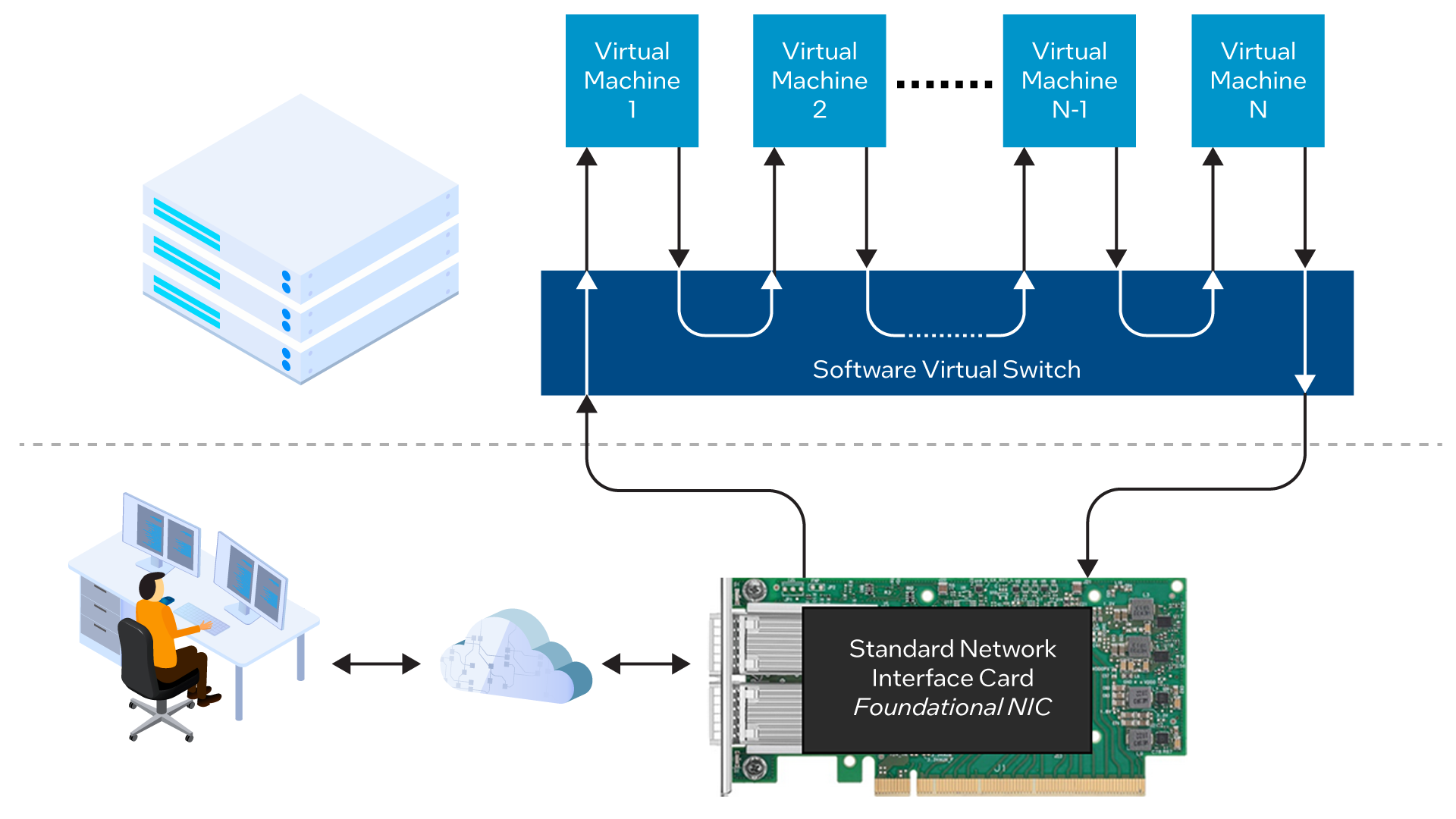
Traditionally, a virtualized data plane is implemented completely in software and many of its compute cycles are consumed by running a virtual switch (vSwitch) which routes network traffic between VMs. Since each vSwitch operation requires a significant number of CPU cycles, this architecture can introduce unacceptable latency into the system and may also prevent the system from achieving the overall performance or throughput required. At the same time, a CPU that is heavily utilized running the virtual data plane will have fewer cores available for running applications and services, increasing the number of servers required to support the data center workload, and increasing both CAPEX and OPEX. See Figure 1.
Leveraging Intel® FPGA IPU-Based Architecture
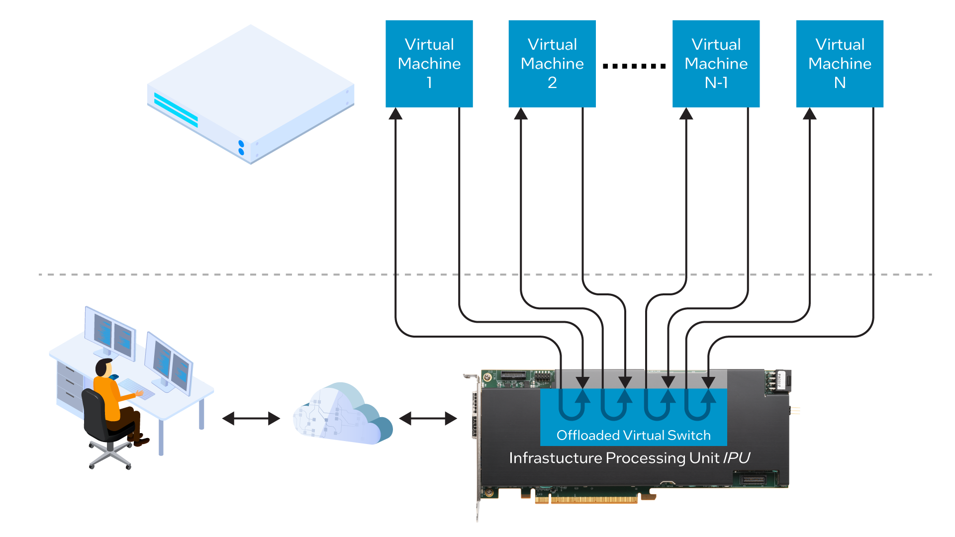
A more efficient and cost-effective system-level architecture leverages an Intel FPGA IPU to offload the vSwitch from the server CPU, freeing up the server CPU for running applications and services.
The IPU, which replaces the standard Network Interface Card (NIC) in the data center server, implements the vSwitch in hardware, using a programmable FPGA (Field Programmable Gate Array) to run the data plane in conjunction with a general-purpose CPU that runs the control plane. The vSwitch presents an industry-standard API (Application Programming Interface) to the VMs, ensuring that no changes need to made to the VMs themselves when taking advantage of this architecture. See Figure 2.
The IPU-based architecture delivers three key benefits for a data center running microservices-based applications:
-
Ultra-low latency, which minimizes the delay traffic between the microservices;
-
High performance, which maximizes the overall throughput of the system and application;
-
Optimum server CPU utilization with no server CPU cores consumed by the vSwitch data plane, which minimizes the total number of servers required for the overall workload, also minimizing data center CAPEX and OPEX.
MIT Analysis
To quantify the benefits of vSwitch offload in real-world scenarios, Massachusetts Institute of Technology (MIT) analyzed the performance of two microservices-based use cases, comparing the results from using a traditional software-based vSwitch with those obtained using an Intel IPU running virtualized data plane software from Napatech, a leading provider of SmartNIC and IPU solutions. These two use cases were a publish-subscribe “pub-sub” application that uses message passing for data transfers across multiple tiers and a three-tier TCP application comprising a web server, in-memory cache, and back-end database. The results of this benchmarking initiative are documented in the paper “Microservice Benchmarking on Intel IPUs running Napatech Software” published by MIT.
Pub-Sub Application Performance Analysis
A pub-sub application, short for "publish-subscribe application," is a messaging pattern commonly used in distributed systems to facilitate the communication and coordination between different components or services. The pub-sub pattern allows for asynchronous and decoupled communication, where senders of messages, known as publishers, do not need to know the specific recipients, known as subscribers. Pub-sub applications are applicable to use cases such as:
-
Seating reservation systems that create a floor plan, assign seats to it and then manage the live seat-booking events. As clients buy tickets, the pub-sub system updates the floor plan everywhere in real time and keeps the distributed cache system in sync. Clients never end up requesting a seat only to find out someone had bought it while they were still in the browsing/shopping phase.
-
Educational tools that allow students to participate in a classroom via a web-based app, where clients often encounter issues such as unreliable WiFi or unpredictable cellular networks. The pub-sub system recovers their connection when they rejoin the network and is able to handle rapid changes in the number of online participants.
-
Financial applications such as the distribution of market data including stock prices, market indices, trade data and order book updates to subscribers within an organization.
-
Internet of Things (IoT) systems, where pub-sub facilitates communication between numerous IoT devices and enables efficient data dissemination. Sensors publish data, then subscribers can receive and process that data in real-time.
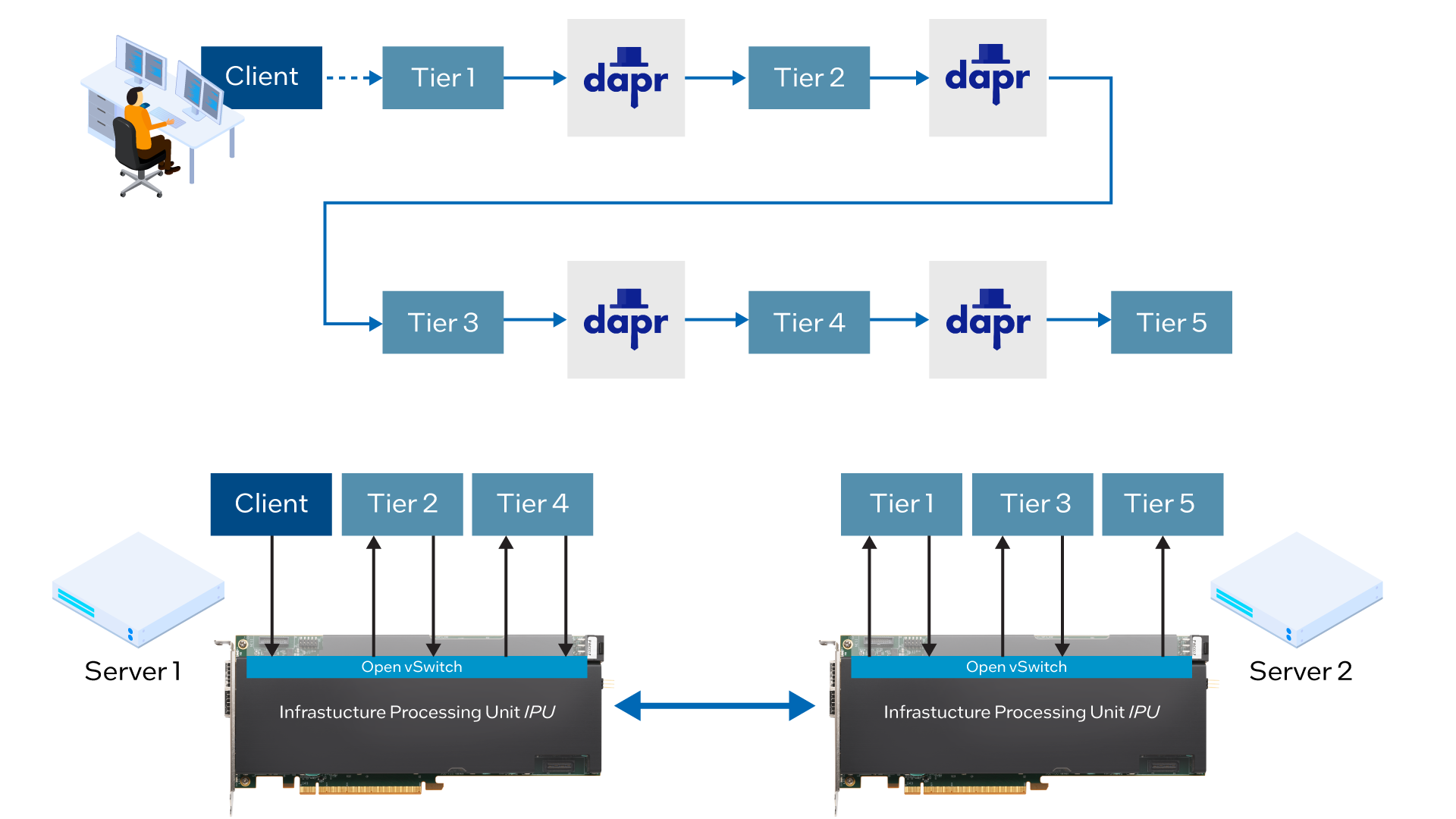
For this analysis, MIT evaluated a five-tier chain topology developed with a pub-sub communication model from Dapr, which is a portable, event-driven runtime that enables developers to build resilient, stateless and stateful applications that run both on the cloud and edge, while supporting a diversity of languages and developer frameworks. Each tier performs CPU-intensive computation for a user-specified amount of time, before broadcasting its output to the downstream tier. See Figure 3.
Within the five-tier pub-sub application, the placement of services across the two OVS-enabled servers ensures that dependent services are running on different physical machines, so that all traffic between tiers passes across the IPUs, when enabled.
MIT analyzed the performance of the pub-sub system both with and without the IPU-based offload, measuring the messaging latency across varying loads which are expressed as thousands of queries per second (kQPS). See Figure 4.
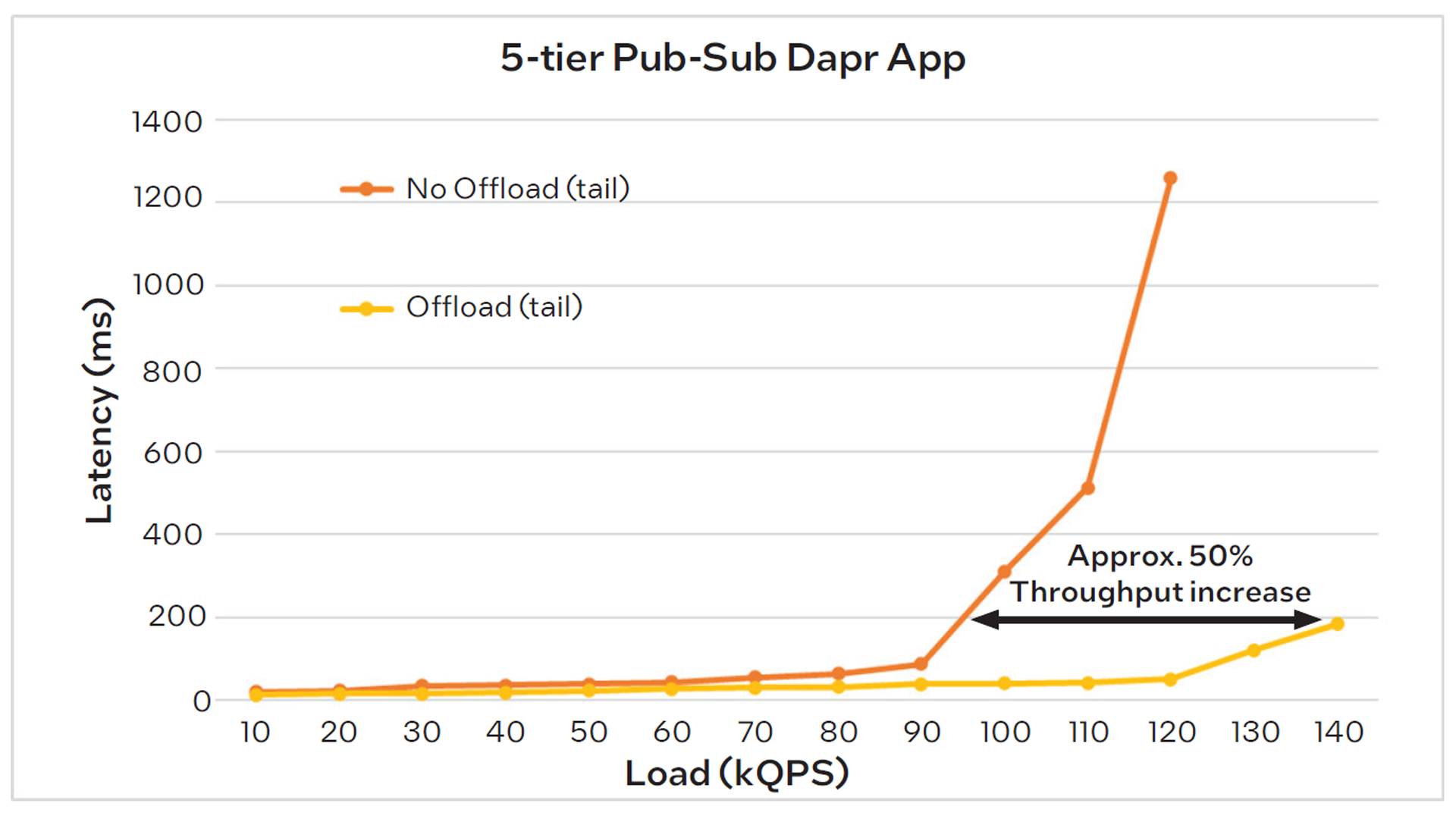
When offload is disabled and considering tail (i.e. worstcase) latency, the application starts to saturate at 90kQPS, as indicated by the inflection point in the graph. Beyond that load level, the system can no longer efficiently keep up with requests, most likely due to packet drops that result in TCP retransmissions. When offload is enabled, however, the system is still keeping up with requests at a load of 140kQPS, the maximum rate used in this test, indicating that the IPU enables a 50% increase in throughput while maintaining acceptable tail latency. This represents a significant improvement in system capacity, resulting in savings of 30-40% in both total server cost and energy consumption.
Three-Tier TCP Application Performance Analysis
A three-tier TCP (Transmission Control Protocol) application refers to a software architecture design that divides an application into three logical layers or tiers, each responsible for specific functions. These tiers are typically referred to as the presentation tier, application tier, and data tier. The TCP protocol is used for communication between these tiers:
-
Presentation Tier: Also known as the user interface (UI) tier, this layer is responsible for presenting the application’s information to users and receiving their inputs. It deals with graphical user interface (GUI) components, such as web pages, forms, or desktop interfaces. The presentation tier communicates with the application tier to retrieve or update data as necessary.
-
Application Tier: The application tier contains the business logic and processing logic of the application. It handles the core functionality and performs tasks such as data validation, business rules enforcement, and application-specific operations. This tier processes the requests from the presentation tier and communicates with the data tier to retrieve or store data.
-
Data Tier: The data tier, also known as the data access layer or database tier, is responsible for managing the storage and retrieval of data. It handles interactions with the database systems, such as querying and updating data. The data tier receives requests from the application tier and returns the requested data or performs the necessary data modifications.
In a three-tier TCP application, the communication between these tiers is facilitated using the TCP protocol. TCP ensures reliable and ordered delivery of data between the tiers, providing a connection-oriented and stream-based communication mechanism. By separating the application into these three tiers, the three-tier TCP architecture allows for modularity, scalability, and easier maintenance of the application. Each tier can be developed and scaled independently, facilitating flexibility and reusability of components.
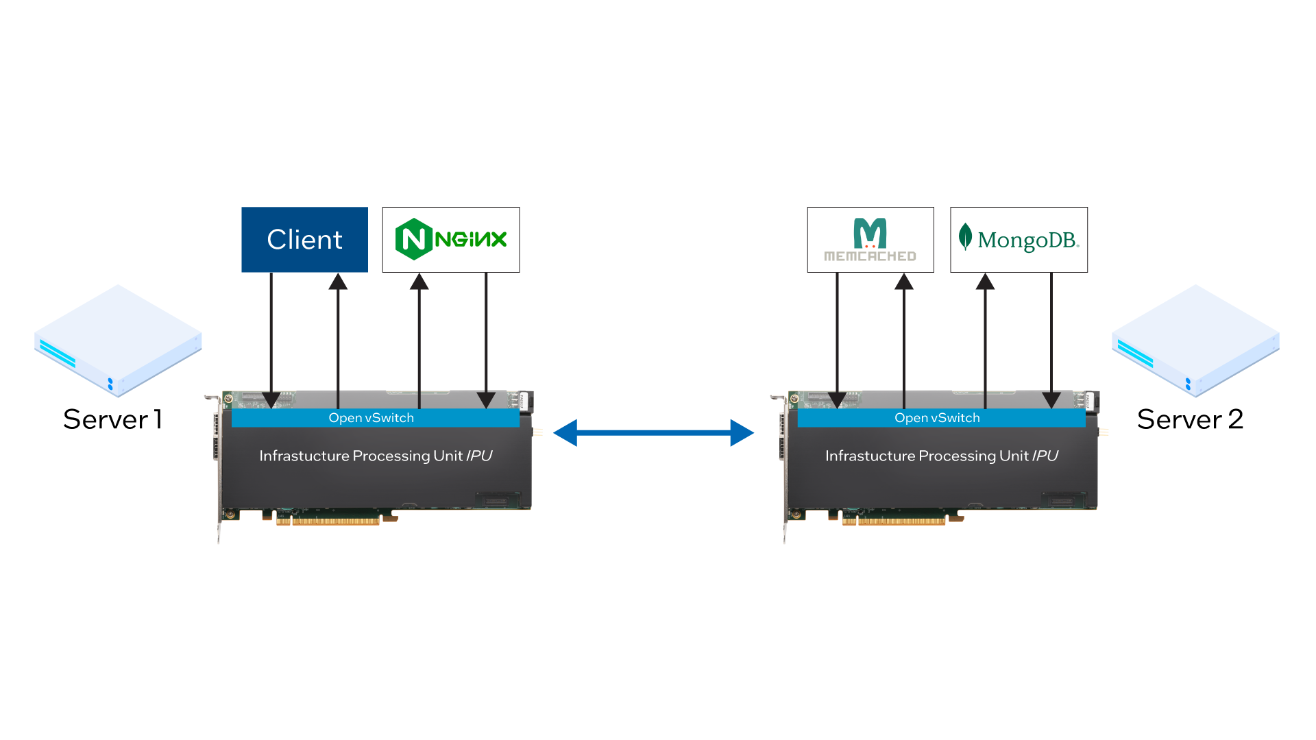
For this analysis, MIT evaluated a three-tier application with NGINX as the front-end web server, Memcached as the in-memory caching tier, and MongoDB as the back-end database with persistent storage. Clients interact with NGINX, which checks if a key-value pair is cached in Memcached and, if so, returns the value to the client. If not, NGINX interfaces with MongoDB to fetch the output and additionally cache it in Memcached. See Figure 5.
MIT analyzed the performance of the three-tier TCP application both with and without the IPU-based offload, measuring the messaging latency across varying loads which, as in the previous example, are expressed as thousands of queries per second (kQPS). See Figure 6.
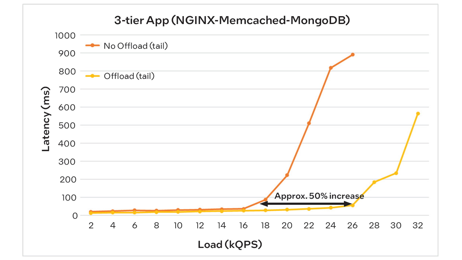
When offload is disabled and considering tail (i.e. worst-case) latency, the application starts to saturate at approximately 17kQPS, as indicated by the inflection point in the graph. Beyond that load level, the system can no longer efficiently keep up with requests, most likely due to packet drops that result in TCP retransmissions. When offload is enabled, however, saturation does not start until a load of 26kQPS, indicating that the IPU enables a 53% increase in throughput while maintaining acceptable tail latency. Like the previous example, this represents a significant improvement in system capacity, resulting in savings of 30-40% in both total server cost and energy consumption.
System Configuration
The system configuration used by MIT for microservices benchmarking was as follows:
- Two Inspur dual-socket servers, each featuring an Intel® Xeon® Gold 6338 Processor with 48MB cache, running at 2.0 GHz with 3.2 GHz turbo speed. Each server was configured with 512GB memory, a 480GB boot drive, dual 1.6TB P6410 NVMe storage modules and one 10G Intel® Ethernet Controller XL710 NIC.
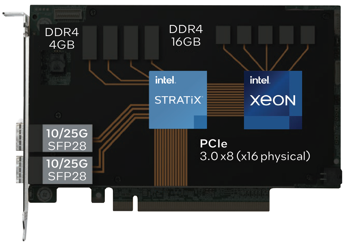
- In addition to the standard NIC, each server was configured with one Intel IPU C5000X adapter with dual 10/25G SFP28 ports and a PCIe 3.0 host interface, based on an Intel® Stratix® FPGA and Intel® Xeon® D System-on-Chip (SoC). See Figure 7.
- Each IPU was running the Link-Virtualization 4.3.3 software from Napatech, providing an offloaded and accelerated virtualized data plane including functions such as Open vSwitch (OVS), VirtIO support, live migration, VM-to-VM mirroring, VLAN/VxLAN encapsulation/decapsulation, Q-in-Q, RSS load balancing, link aggregation and Quality of Service (QoS).