Visible to Intel only — GUID: bun1502301548205
Ixiasoft
1.5.1. Step 1: Getting Started
1.5.2. Step 2: Create Design Partitions
1.5.3. Step 3: Allocate Placement and Routing Regions
1.5.4. Step 4: Add the Partial Reconfiguration Controller IP
1.5.5. Step 5: Define Personas
1.5.6. Step 6: Create Revisions
1.5.7. Step 7: Compile the Base Revision
1.5.8. Step 8: Set Up PR Implementation Revisions
1.5.9. Step 9: Change the SUPR Logic
1.5.10. Step 10: Program the Board
1.5.11. Modifying the SUPR Partition
Visible to Intel only — GUID: bun1502301548205
Ixiasoft
1.5.3. Step 3: Allocate Placement and Routing Regions
For every base revision that you create, the Compiler uses the PR partition region allocation to place the corresponding persona core in the reserved region. Follow these steps to locate and assign a PR region in the device floorplan for your base revision:
- In the Project Navigator Hierarchy tab, right-click the u_blinking_led instance, and then click Logic Lock Region > Create New Logic Lock Region. The region appears in the Logic Lock Regions window.
- Specify a region Width of 5 and Height of 4.
- Specify the placement region coordinates for u_blinking_led in the Origin column. The origin corresponds to the lower-left corner of the region. Specify the Origin as X57_Y6. The Compiler calculates (X62_Y9) as the top-right coordinate.
- Enable the Reserved and Core-Only options for the region.
- Double-click the Routing Region option. The Logic Lock Routing Region Settings dialog box appears.
- For the Routing Type, select Fixed with expansion. This option automatically assigns an Expansion length of one.
- Repeat the previous steps to allocate the following resources for the u_top_counter partition:
- Height—4
- Width—5
- Origin—X64_Y6
- Routing Region— Fixed with expansion with Expansion length of one.
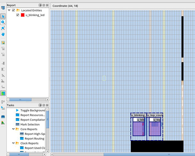
Note: The routing region must be larger than the placement region, to provide extra flexibility for the Compiler's routing stage, when the Compiler routes different personas. - Your placement region must enclose the blinking_led logic. To select the placement region by locating the node in Chip Planner, right-click the u_blinking_led region name in the Logic Lock Regions window, and then click Locate Node > Locate in Chip Planner.
- Under Partition Reports, double-click Report Design Partitions. The Chip Planner highlights and color codes the region.
Alternatively, adding the following lines to blinking_led.qsf creates these regions:
set_instance_assignment -name PARTITION supr_partition -to u_top_counter
set_instance_assignment -name PARTIAL_RECONFIGURATION_PARTITION ON -to \
     u_top_counter
set_instance_assignment -name PLACE_REGION "X64 Y6 X68 Y9" -to \
     u_top_counter
set_instance_assignment -name RESERVE_PLACE_REGION ON -to u_top_counter
set_instance_assignment -name CORE_ONLY_PLACE_REGION ON -to u_top_counter
set_instance_assignment -name ROUTE_REGION "X63 Y5 X69 Y10" -to \
     u_top_counter
set_instance_assignment -name PARTITION pr_partition -to u_blinking_led
set_instance_assignment -name PARTIAL_RECONFIGURATION_PARTITION ON -to \
     u_blinking_led
set_instance_assignment -name RESERVE_PLACE_REGION ON -to u_blinking_led
set_instance_assignment -name CORE_ONLY_PLACE_REGION ON -to u_blinking_led
set_instance_assignment -name PLACE_REGION "X57 Y6 X62 Y9" -to \
     u_blinking_led
set_instance_assignment -name ROUTE_REGION "X56 Y5 X61 Y10" -to \
     u_blinking_led