Visible to Intel only — GUID: bpo1572267983627
Ixiasoft
1. Answers to Top FAQs
2. Overview of the Intel® FPGA Power and Thermal Calculator
3. Estimating Power Consumption with the Intel® FPGA Power and Thermal Calculator
4. Intel® FPGA Power and Thermal Calculator Graphical User Interface
5. Intel® FPGA Power and Thermal Calculator Pages
6. Factors Affecting the Accuracy of the Intel® FPGA PTC
7. Intel® FPGA Power and Thermal Calculator User Guide Archive
8. Document Revision History for the Intel® FPGA Power and Thermal Calculator User Guide
A. Measuring Static Power
4.2.2.1. Using Design Hierarchies in the Intel® FPGA Power and Thermal Calculator
4.2.2.2. Entering Hierarchy Information Into the Intel® FPGA PTC
4.2.2.3. Exporting, Importing, Duplicating, Renaming, and Deleting Hierarchies in the Intel® FPGA PTC
4.2.2.4. Bulk Editing Hierarchies in the Intel FPGA PTC
5.1. Intel® FPGA PTC - Power Summary/Navigation
5.2. Intel® FPGA PTC - Common Page Elements
5.3. Intel® FPGA PTC - Main Page
5.4. Intel® FPGA PTC - Logic Page
5.5. Intel® FPGA PTC - RAM Page
5.6. Intel® FPGA PTC - DSP Page
5.7. Intel® FPGA PTC - Clock Page
5.8. Intel® FPGA PTC - PLL Page
5.9. Intel® FPGA PTC - I/O Page
5.10. Intel® FPGA PTC - Transceiver Page
5.11. Intel® FPGA PTC - HPS Page
5.12. Intel® FPGA PTC - Crypto Page
5.13. Intel FPGA PTC - NOC Page
5.14. Intel® FPGA PTC - HBM Page
5.15. Intel® FPGA PTC - Thermal Page
5.16. Intel® FPGA PTC - Report Page
Visible to Intel only — GUID: bpo1572267983627
Ixiasoft
5.8. Intel® FPGA PTC - PLL Page
Each row in the PLL data entry page of the Intel® FPGA Power and Thermal Calculator (PTC) represents one or more PLLs in the device.
Supported PLL types are family dependent, as outlined in the PLL Page Information table.
Figure 41. PLL Page
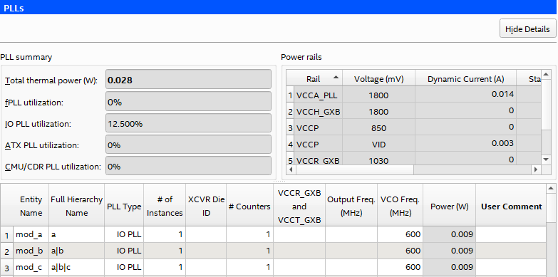
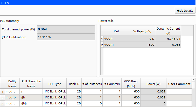
Figure 42. PLL Page ( Intel Agilex® Devices)
| Column Header | Description |
|---|---|
| Total thermal power (W) | Reports the total thermal power (in W). |
| fPLL utilization | Reports the percentage of fPLL utilization. (This field is available for Intel® Stratix® 10 devices only.) |
| IO PLL utilization | Reports the percentage of I/O PLL utilization. |
| ATX PLL utilization | Reports the percentage of ATX PLL utilization. (This field is available for Intel® Stratix® 10 devices only.) |
| CMU/CDR PLL utilization | Reports the percentage of CMU/CDR PLL utilization. (This field is available for Intel® Stratix® 10 devices only.) |
| Power rails | Indicated the voltage (mV), dynamic current (A), and standby current (A), for various power rails. |
| Column Heading | Description |
|---|---|
| Entity Name | Specify a name for the PLL entity in this column. This is an optional value. |
| Full Hierarchy Name | Specify the hierarchical path relevant to this entry. This is an optional entry. When entering levels of hierarchy, the pipe character (|) denotes a level of hierarchy. |
| PLL Type | Specifies the type of PLL, which may include the following:
|
| # of Instances | The number of logical PLL instances with this type, counter, voltage, and frequency combination. |
| Bank ID | The I/O bank ID for this row. A bank location can be assigned to PLLs to change how the PLLs are placed, affecting thermals and utilization. (This column is available for Intel Agilex® 7 devices only.) |
| # PLL Blocks | Enter the number of PLL blocks with the same combination of parameters. |
| XCVR Die ID | Specify the transceiver die on which PLLs on this row are located. This field is not applicable for I/O PLLs, nor fabric-feeding I/O PLLs. |
| # Counters | Enter the number of counters of the PLL. |
| VCCR_GXB and VCCT_GXB Voltage | Specify the voltage of the VCCR_GXB and VCCT_GXB rails. This field is not applicable for I/O PLLs, nor fabric-feeding I/O PLLs. |
| Output Freq (MHz) | Specify the output frequency for CMU and ATX PLLs. |
| VCO Freq (MHz) | Specify the internal VCO operating frequency for PLLs. |
| Total Power (W) | Shows the total estimated power for this row (in W). |
| User Comments | Enter any comments. This is an optional entry. |
For more information about the PLLs available in Intel Agilex® 7 devices, refer to the Intel Agilex® 7 Clocking and PLL User Guide.
Related Information