1.9. Additional Chaining DMA Commands
In addition to the parameter settings to control the chaining DMA, the GUI includes five other commands. The following table describes these commands. The position of the slider control changes the command.
| Command | Options | Description |
|---|---|---|
| Run endpoint DMA | Write only Read only Read then write Write then read Read and write | Writes transfers data from the FPGA to system memory. Reads transfer data from system memory to the FPGA. |
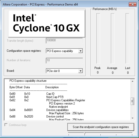
| Scan the endpoint configuration space registers | Type 0 Configuration PCI Express capability MSI capability Power management capability | Reports the byte address offset, value and a description of the selected register set. |
| Run target read | At endpoint address From 0x0 to endpoint address | Programs the Root Port of the motherboard’s PCI Express chipset to read from the FPGA’s memory, as follows:
|
| Run target write | At endpoint address From 0x0 to endpoint address | Programs the Root Port of the motherboard’s PCI Express chipset to write to the FPGA’s memory, as follows:
|
Figure 7. Scan the Endpoint Configuration Space Registers