1.2. Using the Native PHY IP Core for QPI
Use the Native PHY IP core to implement QPI for a low latency requirement.
The Native PHY IP core provides direct access to the PMA from the FPGA fabric in PMA Direct mode. Consequently, the latency for transmitted and received data is very low.
Use the following steps to implement QPI with the necessary options and settings, using the Native PHY IP core:
- Configure the Native PHY IP core
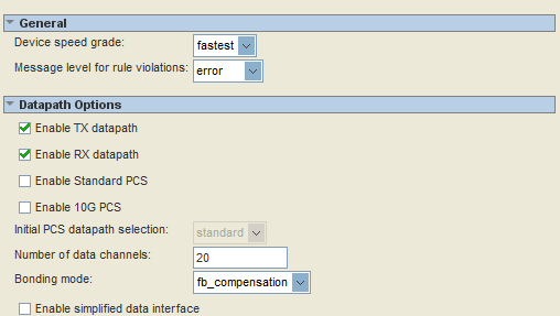
After the Stratix V Transceiver Native PHY IP core opens in the MegaWizard™ Plug-In Manager, the General tab and block diagram appear. The General tab contains the general settings for the Native PHY IP core.
For example, design an 8 Gbps QPI as a full-width link using the Datapath Options.
- Select Enable TX datapath and Enable RX datapath.
- Set the Number of data channels to 20.
- Set the Bonding mode to fb_compensation.
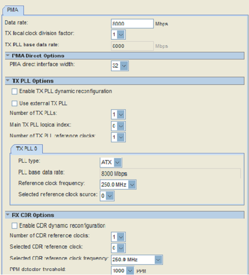
- In the PMA tab, input the Data rate as 8000 Mbps.
- In PMA Direct Options, set the PMA direct interface width to 32.
- In the TX PLL 0 tab, select the PLL type as ATX, and set the Reference clock frequency to 250.0 MHz.
- In RX CDR Options, set the Selected CDR reference clock frequency to 250.0 MHz.
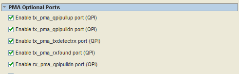
- In PMA Optional Ports, enable the ports for the QPI features:
- tx_pma_qpipullup
- tx_pma_qpipulldn
- tx_pma_txdetectrx
- tx_pma_rxfound
- rx_pma_qpipulldn
- Click Finish in the MegaWizard Plug-In Manager.
- Enable the QPI Setting for the Transceiver
Open the <project_name> .qsf file and input the following settings.
Termination
- set_instance_assignment -name XCVR_IO_PIN_TERMINATION 85_OHMS -to tx_serial_data[0]
- set_instance_assignment -name XCVR_IO_PIN_TERMINATION 85_OHMS -to rx_serial_data[0]
QPI Enable
- set_instance_assignment -name XCVR_RX_QPI_ENABLE ON -to rx_serial_data
- set_instance_assignment -name XCVR_TX_QPI_EN ON -to tx_serial_data
DC Coupling Support
- set_instance_assignment -name XCVR_TX_VCM_CTRL_SRC DYNAMIC_CTL -to tx_serial_data[0]
- set_instance_assignment -name XCVR_RX_INPUT_VCM_SEL LOW_VCM -to rx_serial_data[0]
Link Detection
- set_instance_assignment -name XCVR_TX_RX_DET_OUTPUT_SEL RX_DET_QPI_OUT -to tx_serial_data[0]
Note: For more information about QSF settings, refer to the Quartus Settings File Reference Manual. - Link the Detection Design Flow
To enable RX link detection at the transmitter side, the transmitter driver must be set as tri-state. During the normal data transferring state, the transmitter driver must be enabled.
The rtx_pdb bit is used to control the transmitter buffer in tri-state. It can be accessed through the Streamer mode 3 in the transceiver reconfiguration controller.

Bit[15] of rtx_pdb must be set to 0 before the link detection function is triggered. Writing a 1 to the rtx_pdb bit will set the transmitter buffer in normal mode. The other bits at this address cannot be modified.