Tandem Motion-Power 48 V Board Jumper Settings
| Jumper | Axis | Function |
|---|---|---|
| J6 | DRV0 | EnDAT operation |
| J7 | DRV0 | EnDAT operation |
| J8 | DRV0 | Encoder power supply selection |
| J10 | DRV0 | Quadrature encoder A source |
| J11 | DRV0 | Hall sensor U source |
| J12 | DRV0 | Serial encoder Rx source |
| J13 | DRV0 | Quadrature encoder B source |
| J14 | DRV0 | Hall sensor V source |
| J15 | DRV0 | Serial encoder Tx source |
| J16 | DRV0 | Quadrature encoder Z source |
| J17 | DRV0 | Hall sensor W source |
| J18 | DRV0 | Serial encoder CLK source |
| J20 | DRV1 | EnDAT operation |
| J21 | DRV1 | EnDAT operation |
| J22 | DRV1 | Encoder power supply selection |
| J24 | DRV1 | Quadrature encoder A source |
| J25 | DRV1 | Hall sensor U source |
| J26 | DRV1 | Serial encoder Rx source |
| J27 | DRV1 | Quadrature encoder B source |
| J28 | DRV1 | Hall sensor V source |
| J29 | DRV1 | Serial encoder Tx source |
| J30 | DRV1 | Quadrature encoder Z source |
| J31 | DRV1 | Hall sensor W source |
| J32 | DRV1 | Serial encoder CLK source |
| J39 | DRV0 | RDC BIST |
| J40 | DRV0 | Resolver excitation voltage |
| J42 | DRV1 | RDC BIST |
| J43 | DRV1 | Resolver excitation voltage |
Quadrature Encoder and Hall Sensor Operation
You can select quadrature encoder and Hall sensor motor feedback operation by populating these six jumpers, per axis. You can set up the Tamagawa RDC to emulate a quadrature encoder.
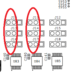
Figure 3. DRV0 Motor Feedback Jumpers, Quadrature and Hall OperationLocated midboard.

J10, J13 and J16 select the A, B and Z quadrature paths for DRV0 motor.
J11, J14 and J17 select the U, V and W Hall sensor paths for DRV0 motor.
Figure 4. DRV1 Motor Feedback Jumpers Quadrature and Hall operationLocated middle-bottom of board.
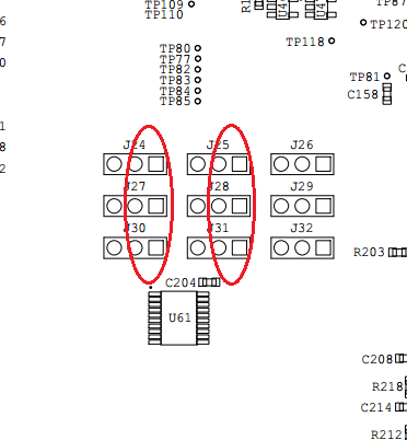
J24, J27 and J30 select the A, B and Z quadrature path for DRV1 motor.
J25, J28 and J31 select the U, V and W Hall sensor path for DRV1 motor.
RDC Quadrature Encoder Emulation Operation
You can setup the Tamagawa RDC to emulate a quadrature encoder and or Hall sensor encoder.
Figure 5. DRV0 Motor Feedback Jumpers Quadrature Emulation OperationLocated mid board.
J10, J13 and J16 select the A, B and Z paths for DRV0 Resolver.
J11, J14 and J17 select the U, V and W paths for DRV0 Resolver.
Figure 6. DRV1 Motor Feedback Jumpers Quadrature Emulation OperationLocated middle-bottom of board.
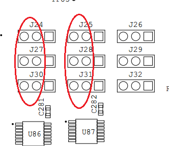
J24, J27 and J30 select the A, B and Z paths for DRV1 Resolver.
J25, J28 and J31 select the U, V and W paths for DRV1 Resolver.
BiSS and EnDAT Operation
You can select BiSS or EnDAT position feedback data coming from the motor.
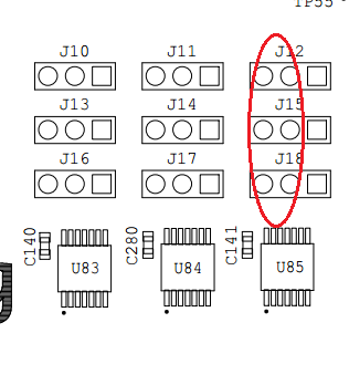
Figure 7. DRV0 Motor Feedback Jumpers BiSS and EnDAT OperationLocated mid board.
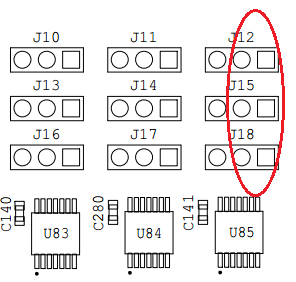
J12, J15 and J18 select the RX, TX and CLK paths for the DRV0 motor.
Figure 8. DRV1 Motor Feedback Jumpers BiSS and EnDAT OperationLocated middle-bottom of board.
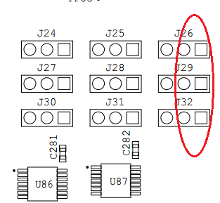
J26, J29 and J32 select the RX, TX and CLK paths for the DRV1 motor.
Note: In addition to the feedback path jumpers, you must set some additional jumpers for EnDAT operation. For BiSS operation you must remove these jumpers.
Figure 9. DRV0 Feedback Data Flow Control Jumpers EnDAT operationLocated mid board.
J6 and J7 select EnDAT for DRV0.
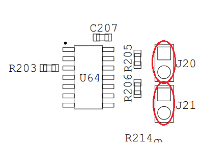
Figure 10. DRV1 Feedback Data Flow Control Jumpers EnDAT OperationLocated middle-bottom of board.

J20 and J21 select EnDAT for DRV1.
RDC Serial Feedback Operation
The Tamagawa RDC can be set up to provide serial feedback data.
Figure 11. DRV0 Motor Feedback Jumpers RDC Serial FeedbackLocated mid board
J12, J15 and J18 select the RX, TX and CLK paths for the DRV0 Resolver serial data.
Figure 12. DRV1 Motor Feedback Jumpers RDC Serial FeedbackLocated middle-bottom of board.
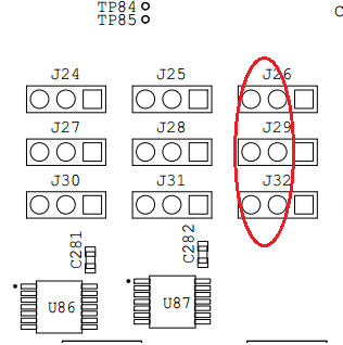
J26, J29 and J32 select the RX, TX and CLK paths for the DRV1 Resolver serial data.
Encoder Power Supply Selection
You can select the power supply voltage connected for the encoder interface. The available options are 24V, 12V, 5V and 3.3V.
Figure 13. DRV0 Encoder Power Selector, mid board right edgeMid board right edge.
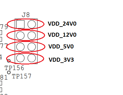
J8 selects the voltage for encoders on DRV0.
Note: Do not fit more than one jumper link at a time to J8. Do not fit jumpers to J8 in any other orientation.
Figure 14. DRV1 Encoder Power SelectorBottom of board right edge.
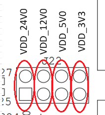
J22 selects the voltage for encoders on DRV1.
Note: Do not fit more than one jumper link at a time to J22. Do not fit jumpers to J22 in any other orientation.
Tamagawa RDC Built-In Self Test (BIST)
The Tamagawa RDC has a BIST feature that you can access.
the population of the no BIST position is not required as the board has an internal pull-down resistor in the RDC to disable BIST.
Intel reference designs do not support the RDC BIST feature.
Figure 15. DRV0 RDC BIST Jumper Located mid board
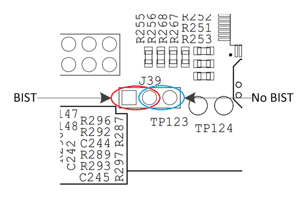
J39 Selects BIST operation for DRV0 RDC. (DRV0) and J42 (DRV1).
Figure 16. DRV1 RDC BIST Jumper Located bottom of board
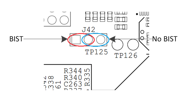
J42 Selects BIST operation for DRV1 RDC.
Resolver Excitation Voltage Selection
You can select the resolver circuitry excitation voltage to be either 12V or 24V.
Note: The default excitation voltage requirement for the Tamagawa motors supplied with the Tandem Motion-Power 48 V Board Kit is 12 V.
Figure 17. DRV0 Resolver Excitation Voltage Selection Located mid board.
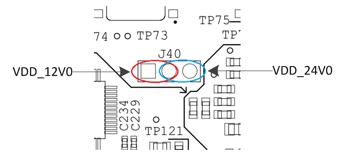
J40 selects the excitation voltage for DRV0.
Figure 18. DRV1 Resolver Excitation Voltage Selection Located at bottom of board.

J43 selects the excitation voltage for DRV1.
I/O Voltage Supply
R378, R377, R376