Visible to Intel only — GUID: ijw1661937234333
Ixiasoft
1. About the Video and Vision Processing Suite
2. Getting Started with the Video and Vision Processing IPs
3. Video and Vision Processing IPs Functional Description
4. Video and Vision Processing IP Interfaces
5. Video and Vision Processing IP Registers
6. Video and Vision Processing IPs Software Programming Model
7. Protocol Converter Intel® FPGA IP
8. 1D LUT Intel® FPGA IP
9. 3D LUT Intel® FPGA IP
10. AXI-Stream Broadcaster Intel® FPGA IP
11. Bits per Color Sample Adapter Intel FPGA IP
12. Black Level Correction Intel® FPGA IP
13. Black Level Statistics Intel® FPGA IP
14. Chroma Key Intel® FPGA IP
15. Chroma Resampler Intel® FPGA IP
16. Clipper Intel® FPGA IP
17. Clocked Video Input Intel® FPGA IP
18. Clocked Video to Full-Raster Converter Intel® FPGA IP
19. Clocked Video Output Intel® FPGA IP
20. Color Plane Manager Intel® FPGA IP
21. Color Space Converter Intel® FPGA IP
22. Defective Pixel Correction Intel® FPGA IP
23. Deinterlacer Intel® FPGA IP
24. Demosaic Intel® FPGA IP
25. FIR Filter Intel® FPGA IP
26. Frame Cleaner Intel® FPGA IP
27. Full-Raster to Clocked Video Converter Intel® FPGA IP
28. Full-Raster to Streaming Converter Intel® FPGA IP
29. Genlock Controller Intel® FPGA IP
30. Generic Crosspoint Intel® FPGA IP
31. Genlock Signal Router Intel® FPGA IP
32. Guard Bands Intel® FPGA IP
33. Histogram Statistics Intel® FPGA IP
34. Interlacer Intel® FPGA IP
35. Mixer Intel® FPGA IP
36. Pixels in Parallel Converter Intel® FPGA IP
37. Scaler Intel® FPGA IP
38. Stream Cleaner Intel® FPGA IP
39. Switch Intel® FPGA IP
40. Tone Mapping Operator Intel® FPGA IP
41. Test Pattern Generator Intel® FPGA IP
42. Unsharp Mask Intel® FPGA IP
43. Video and Vision Monitor Intel FPGA IP
44. Video Frame Buffer Intel® FPGA IP
45. Video Frame Reader Intel FPGA IP
46. Video Frame Writer Intel FPGA IP
47. Video Streaming FIFO Intel® FPGA IP
48. Video Timing Generator Intel® FPGA IP
49. Vignette Correction Intel® FPGA IP
50. Warp Intel® FPGA IP
51. White Balance Correction Intel® FPGA IP
52. White Balance Statistics Intel® FPGA IP
53. Design Security
54. Document Revision History for Video and Vision Processing Suite User Guide
29.4.1. Achieving Genlock Controller Free Running (for Initialization or from Lock to Reference Clock N)
29.4.2. Locking to Reference Clock N (from Genlock Controller IP free running)
29.4.3. Setting the VCXO hold over
29.4.4. Restarting the Genlock Controller IP
29.4.5. Locking to Reference Clock N New (from Locking to Reference Clock N Old)
29.4.6. Changing to Reference Clock or VCXO Base Frequencies (switch between p50 and p59.94 video formats and vice-versa)
29.4.7. Disturbing a Reference Clock (a cable pull)
Visible to Intel only — GUID: ijw1661937234333
Ixiasoft
37.3.1. Coefficient Selection
If you select polyphase scaling for the Scaler IP, the coefficients that the scaling filters use are read from a memory. You must define the contents of this memory. Either specify fixed horizontal and vertical coefficient sets in the Horizontal coefficient function and Vertical coefficient function parameters or turn on Update coefficients at runtime. If you turn on Update coefficients at runtime, you can write whatever values you want to the coefficient memory. If you already have well defined coefficient sets that you use, the flexibility in the scaler to select the desired number of filter taps and phases should allow you to continue with these. If you are new to scaling, read the following guidance on coefficient selection.
Generally, the set of coefficients that the IP writes to filter phase 0 yield a low-pass filter, with most weight in generating the output pixel value given to the pixel value in tap . The function is centered at tap . The coefficients the IP writes to the other phases are then just phase-shifted versions of this function (hence the name phase for each coefficient address), with the function centered at a point that is shifted by 1/ num_of_pixels of a pixel with every subsequent phase.
Figure 88. 2-lobe Lanczos function at 3 different phases This figure shows an example of how a function is progressively phase-shifted to create the coefficients for each scaling filter phase. The figure shows a 4 tap filter, with the taps shown on the x-axis
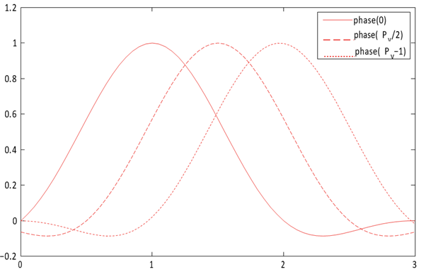
The Lanczos function is a common function that defines scaling coefficients. The Lanczos function is a base sinc function, with the primary lobe of a sinc function used as a window function to preserve a given number of lobes of the base sinc. The number of lobes is generally appended to Lanczos when referring to a specific variant of the function, so a Lanczos function where two lobes are preserved is referred to as Lanczos2. In the case where N lobes are preserved, the LanczosN function is defined as:
Equation 8. Coefficient Selection Equation
When using LanczosN coefficients, Intel recommends configuring the scaler filters with the following numbers of taps for the upscale and downscale cases:
- Upscale: 2 × N
- Downscale:
The number of lobes in the Lanczos function affects the frequency response of the filter and, as a result, the quality of the image produced. Generally, Lanczos functions with lower numbers of lobes give a softer frequency response and a resulting image with more blur on the edges, but with less risk of ringing artifacts in the areas immediately around the edges. Conversely, Lanczos functions with higher numbers of lobes give sharper edges but introduce more ringing artifacts. Lanczos2 is a good compromise between minimizing blur and minimizing ringing, but you can experiment with Lanczos3 or Lanczos4 to make your own judgment. The higher the number of lobes, the more filter taps (and therefore FPGA device resources) the design requires to implement the filter correctly. You should experiment with Lanczos1 coefficients for large downscales.