Visible to Intel only — GUID: jba1434040213259
Ixiasoft
1.6.1. Initial Stackup Entry
1.6.2. Using the Correct Number of Power/Ground Via Pairs
1.6.3. Using the Correct Number of Power/Ground Via Pairs and Layer Number
1.6.4. Corrected Number of Power/Ground Via Pairs and Layer Numbers
1.6.5. Moving Supplies to Optimal Layers
1.6.6. Moving Power and Ground Planes Closer Together
1.6.7. Move Decoupling Capacitors to the Top Surface of the PCB
1.6.8. Using X2Y Decoupling Capacitors
1.6.9. Using Ultra–Low ESR Bulk Capacitors
1.6.10. Swapping VCC on Layer 9 with VCC, VCCT_GXB, and VCCR_GXB on Layer 4
1.6.11. Assessing How Much Total Capacitance Might be Required
1.6.12. Using the Core Clock Frequency and Current Ramp Up Period Parameters
1.6.13. Overall Design Study Capacitor Savings
1.6.14. Overall Summary
1.6.15. References
Visible to Intel only — GUID: jba1434040213259
Ixiasoft
1.6.2. Using the Correct Number of Power/Ground Via Pairs
Unless you change manually, the PDN Tool sets the Number of Power/Ground Via Pairs for each power group to the default value defined on the Stackup tab. For this case it is 50 as shown by the figure below.
Figure 9. Incorrect Number of Power/Ground Via Pairs and Layer Number
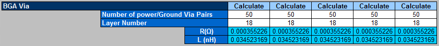
PCB PDN design is highly dependent on the Number of Power/Ground Via Pairs. This contributes to the spreading inductance (Ls) in the PDN design. If the actual Number of Power/Ground Via Pairs in the PCB is less than the number defined in the PDN Tool, the PDN Tool reports optimistic results. It is important to set the correct Number of Power/Ground Via Pairs to match your device and PCB.
Always provide a dedicated via connecting each power and ground pin on the FPGA to the plane. For more information on the importance of the number of power and ground pin pairs refer to Knowledge Database note.
Figure 10. Number of power and ground pin pairs
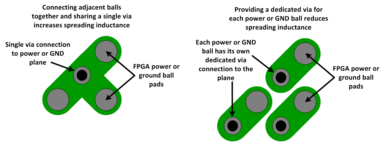
An increase in the Number of Power/Ground Via Pairs between the plane and FPGA reduces spreading inductance (Ls) and increases the high-frequency current delivery efficiency from the plane to the FPGA. This results in increasing the maximum effective frequency of the PCB PDN.