Visible to Intel only — GUID: sxa1468319361863
Ixiasoft
1. About the Drive-On-Chip Design Example for Intel® MAX® 10 Devices
2. Features of the Drive-on-Chip Design Example for Intel® MAX® 10 Devices
3. Getting Started with the Drive-On-Chip Design Example for Intel® MAX® 10 Devices
4. Rebuilding the Drive-On-Chip Design Example for Intel® MAX® 10 Devices
5. About the Scaling of Feedback Signals
6. Motor Control Software
7. Functional Description of the Drive-on-Chip Design Example
8. Achieving Timing Closure on a Motor Control Design
9. Design Security Recommendations
10. Reference Documents for the Drive-on-Chip Design Example
11. Document Revision History for AN 773: Drive-on-Chip Design Example for Intel® MAX® 10 Devices
3.1. Software Requirements for the Drive-On-Chip Design Example for Intel® MAX® 10 Devices
3.2. Hardware Requirements for the Drive-On-Chip Design Example for Intel® MAX® 10 Devices
3.3. Downloading and Installing the Design
3.4. Setting Up the Motor Control Board with your Development Board for the Drive-On-Chip Design Example for Intel® MAX® 10 Devices
3.5. Importing the Drive-On-Chip Design Example Software Project
3.6. Configuring the FPGA Hardware for the Drive-On-Chip Design Example for Intel® MAX® 10 Devices
3.7. Programming the Nios II Software to the Device for the Drive-On-Chip Design Example for Intel® MAX® 10 Devices
3.8. Applying Power to the Power Board
3.9. Debugging and Monitoring the Drive-On-Chip Design Example with System Console
3.10. System Console GUI Upper Pane for the Drive-On-Chip Design Example
3.11. System Console GUI Lower Pane for the Drive-On-Chip Design Example
3.12. Controlling the DC-DC Converter
3.13. Tuning the PI Controller Gains
3.14. Controlling the Speed and Position Demonstrations
3.15. Monitoring Performance
4.1. Changing the Intel® MAX® 10 ADC Thresholds or Conversion Sequence
4.2. Generating the Qsys System
4.3. Compiling the Hardware in the Intel Quartus Prime Software
4.4. Generating and Building the Nios II BSP for the Drive-On-Chip Design Example
4.5. Software Application Configuration Files
4.6. Compiling the Software Application for the Drive-On-Chip Design Example
4.7. Programming the Design into Flash Memory
7.1. Processor Subsystem
7.2. Six-channel PWM Interface
7.3. DC Link Monitor
7.4. Drive System Monitor
7.5. Quadrature Encoder Interface
7.6. Sigma-Delta ADC Interface for Drive Axes
7.7. Intel® MAX® 10 ADCs
7.8. ADC Threshold Sink
7.9. DC-DC Converter
7.10. Motor Control Modes
7.11. FOC Subsystem
7.12. DEKF Technique
7.13. Signals
7.14. Registers
7.11.1. DSP Builder for Intel FPGAs Model for the Drive-on-Chip Designs
7.11.2. Avalon Memory-Mapped Interface
7.11.3. About DSP Builder for Intel FPGAs
7.11.4. DSP Builder for Intel FPGAs Folding
7.11.5. DSP Builder for Intel FPGAs Model Resource Usage
7.11.6. DSP Builder for Intel FPGAs Design Guidelines
7.11.7. Generating VHDL for the DSP Builder Models for the Drive-on-Chip Designs
Visible to Intel only — GUID: sxa1468319361863
Ixiasoft
3.11. System Console GUI Lower Pane for the Drive-On-Chip Design Example
General Tab
Under Data Source:
- In the DSP mode drop-down menu select DSP calculation mode to use (Software Fixed Point; DSP Builder for Intel FPGAs Fixed point; DSP Builder for Intel FPGAs Floating Point or Software Floating Point)
- Under the ADC Type drop-down menu, select the ADC to use for feedback samples (depending on the power board you use)
- Click Show Raw Samples to show raw or scaled samples.
Figure 14. General Tab
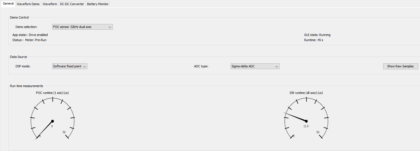
On the Demo selection: drop-down menu select the control algorithm, type of commutation, and update rate to use in the demonstration. The available selections depend on which motor control hardware you use.
The Status: field reports the status of the demonstration. The Runtime: field updates from the application software.
The Run time measurement dials display the processing time of the FOC control loop and the overall Interrupt Service Routine (ISR) processing time, including handling debug trace data. in the currently selected DSP mode.
Waveform Demo Tab
In the Demo drop-down menu select speed, position, or other demonstration.
In the Waveform drop-down menu select the dynamic behavior of the speed or position demo (constant or varying with sine, square, triangle, sawtooth waveform).
Set the nominal speed or position, waveform period, amplitude and offset and click Update Demo.
Note: Large step changes in commands (e.g. using square or triangle wave speed demo) may result in unstable behavior, especially when using sensorless control.
Figure 15. Waveform Demo Tab

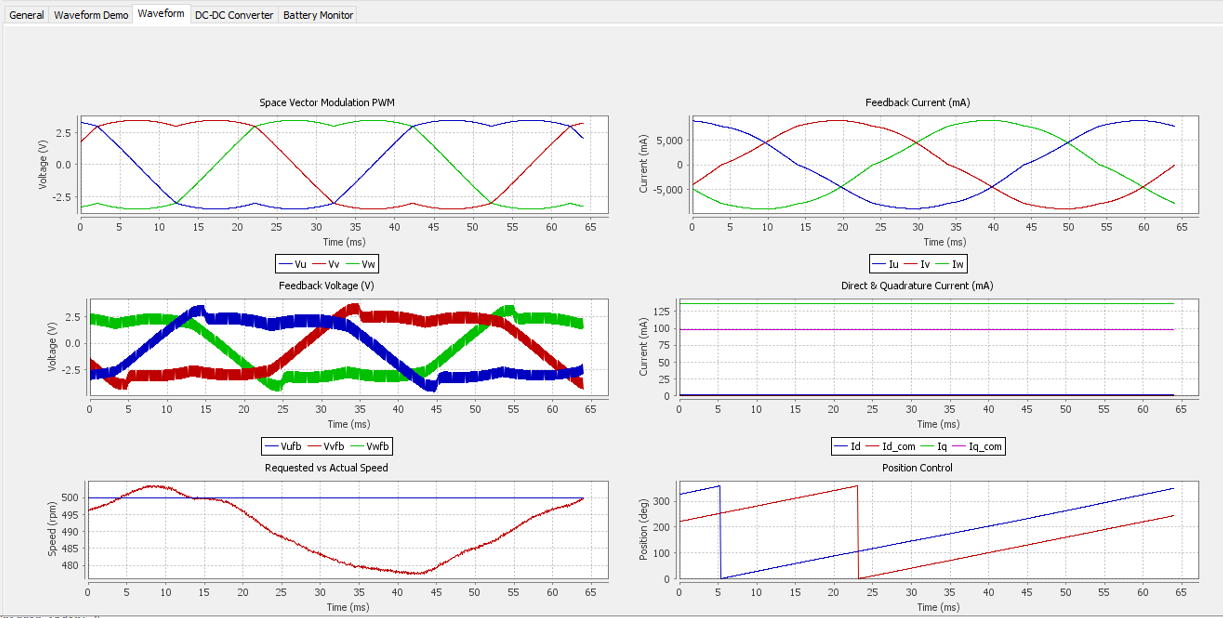
Waveform Tab
The Waveform tab shows the motor control waveform captured as a result of the trigger settings in the Trace Setup tab..
Figure 16. Waveform Tab
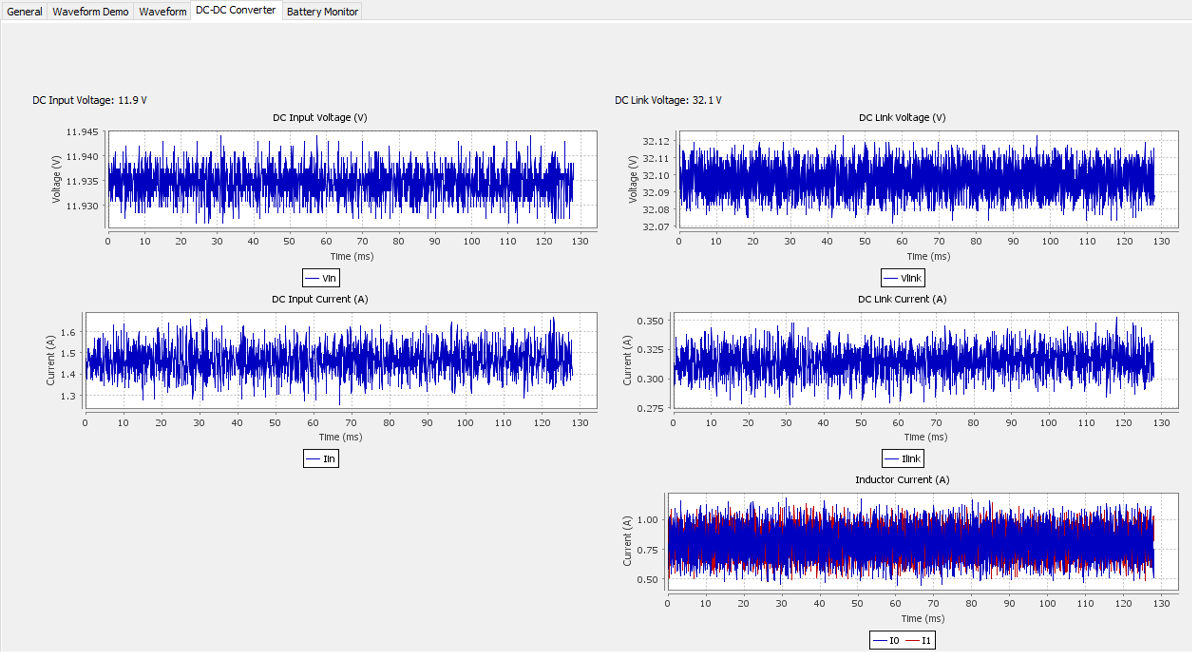
DC-DC Converter Tab
The DC-DC Converter tab shows the DC-DC converter waveforms captured as a result of the trigger settings in the Trace Setup tab.
Figure 17. DC-DC Converter Tab
Demonstration Selection
The Demo selection: drop-down on the General tab selects the demo to run:
- Reset
- Open loop sinusoidal 16 kHz Volts/Hz
- Open loop sinusoidal 32 kHz Volts/Hz
- FOC sensor 16 kHz dual axis
- FOC sensor 32 kHz dual axis
- FOC sensor 64 kHz single axis
- FOC sensorless 16 kHz dual axis
- FOC sensorless 32 kHz single axis
- Trapeziodal Hall sensor 32 kHz dual axis
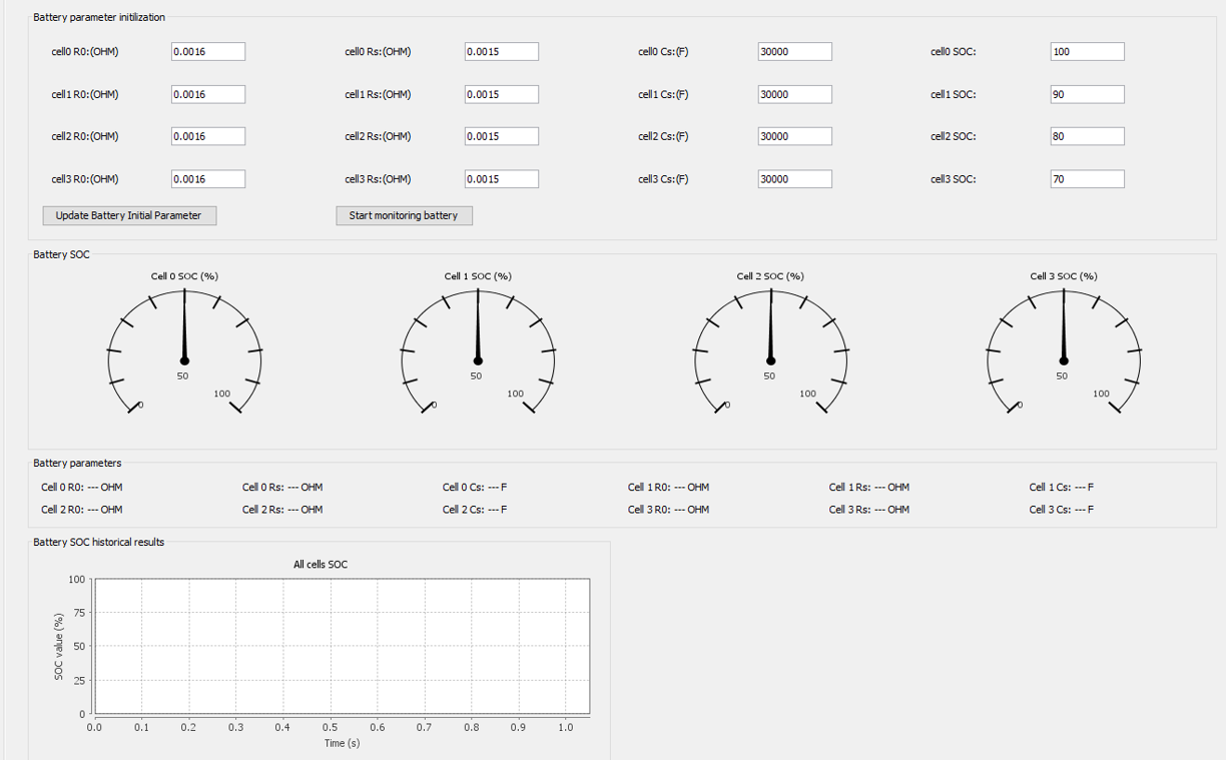
Battery Monitor
The Battery Monitor tab shows the battery initial parameters, battery monitor control, and status of battery, including SOC and parameter values.
Figure 18. Battery Monitor Tab