Visible to Intel only — GUID: bzx1468318525167
Ixiasoft
1. About the Drive-On-Chip Design Example for Intel® MAX® 10 Devices
2. Features of the Drive-on-Chip Design Example for Intel® MAX® 10 Devices
3. Getting Started with the Drive-On-Chip Design Example for Intel® MAX® 10 Devices
4. Rebuilding the Drive-On-Chip Design Example for Intel® MAX® 10 Devices
5. About the Scaling of Feedback Signals
6. Motor Control Software
7. Functional Description of the Drive-on-Chip Design Example
8. Achieving Timing Closure on a Motor Control Design
9. Design Security Recommendations
10. Reference Documents for the Drive-on-Chip Design Example
11. Document Revision History for AN 773: Drive-on-Chip Design Example for Intel® MAX® 10 Devices
3.1. Software Requirements for the Drive-On-Chip Design Example for Intel® MAX® 10 Devices
3.2. Hardware Requirements for the Drive-On-Chip Design Example for Intel® MAX® 10 Devices
3.3. Downloading and Installing the Design
3.4. Setting Up the Motor Control Board with your Development Board for the Drive-On-Chip Design Example for Intel® MAX® 10 Devices
3.5. Importing the Drive-On-Chip Design Example Software Project
3.6. Configuring the FPGA Hardware for the Drive-On-Chip Design Example for Intel® MAX® 10 Devices
3.7. Programming the Nios II Software to the Device for the Drive-On-Chip Design Example for Intel® MAX® 10 Devices
3.8. Applying Power to the Power Board
3.9. Debugging and Monitoring the Drive-On-Chip Design Example with System Console
3.10. System Console GUI Upper Pane for the Drive-On-Chip Design Example
3.11. System Console GUI Lower Pane for the Drive-On-Chip Design Example
3.12. Controlling the DC-DC Converter
3.13. Tuning the PI Controller Gains
3.14. Controlling the Speed and Position Demonstrations
3.15. Monitoring Performance
4.1. Changing the Intel® MAX® 10 ADC Thresholds or Conversion Sequence
4.2. Generating the Qsys System
4.3. Compiling the Hardware in the Intel Quartus Prime Software
4.4. Generating and Building the Nios II BSP for the Drive-On-Chip Design Example
4.5. Software Application Configuration Files
4.6. Compiling the Software Application for the Drive-On-Chip Design Example
4.7. Programming the Design into Flash Memory
7.1. Processor Subsystem
7.2. Six-channel PWM Interface
7.3. DC Link Monitor
7.4. Drive System Monitor
7.5. Quadrature Encoder Interface
7.6. Sigma-Delta ADC Interface for Drive Axes
7.7. Intel® MAX® 10 ADCs
7.8. ADC Threshold Sink
7.9. DC-DC Converter
7.10. Motor Control Modes
7.11. FOC Subsystem
7.12. DEKF Technique
7.13. Signals
7.14. Registers
7.11.1. DSP Builder for Intel FPGAs Model for the Drive-on-Chip Designs
7.11.2. Avalon Memory-Mapped Interface
7.11.3. About DSP Builder for Intel FPGAs
7.11.4. DSP Builder for Intel FPGAs Folding
7.11.5. DSP Builder for Intel FPGAs Model Resource Usage
7.11.6. DSP Builder for Intel FPGAs Design Guidelines
7.11.7. Generating VHDL for the DSP Builder Models for the Drive-on-Chip Designs
Visible to Intel only — GUID: bzx1468318525167
Ixiasoft
3.10. System Console GUI Upper Pane for the Drive-On-Chip Design Example
Trace Setup Tab
On the Trace Setup tab setup select:
- The waveform tracing by specifying a trigger
- Axis to trace
- Trace depth
- A filename to store the trace data.
Click Update Trigger after making any changes. Click Start Trace to start tracing. See the Waveform tab for trace display. When saving trace data to a file, be aware that the design overwrites the file with each trace; it does not append new traces to an existing file.
Figure 8. Trace Setup Tab

Current Control Tab
On the Current Control tab, enter the P (Kp) and I (Ki) coefficients for the current control loop. These quantities are preset to the correct values for the motor type configured in the application software. Click Update Parameters after making a change.
Figure 9. Current Control Tab

Speed Control Tab
On the Speed Control tab, enter the P (Speed Kp) and I (Speed Ki) coefficients for the speed control loop. These quantities are preset to the correct values for the motor type configured in the application software. Click Update Parameters after making a change.
Figure 10. Speed Control Tab

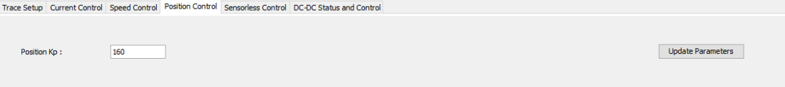
Position Control Tab
On the Position Control tab, enter the P (Position Kp) coefficient for the position control loop. This quantity is preset to the correct values for the motor type configured in the application software. Click Update Parameters after making a change.
Figure 11. Position Control Tab
Sensorless Control Tab
On the Sensorless Control tab, enter the Hys Gain (Hysteresis control gain), Damp Coeff (damping coefficient), natural freq (natural frequency) and Hys Thld (Hysteresis threshold) values for the sensorless control loop. These quantities are preset to the correct values for the motor type configured in the application software. Click Update Parameters after making a change. Modifying these four control parameters may cause the system to become unstable. For example, the motor speed may oscillate or accelerate to a much higher value than the command.
Figure 12. Sensorless Control Tab

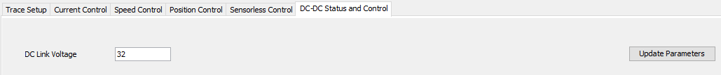
DC-DC Status and Control Tab
The DC-DC Status and Control tab allows you to adjust the target voltage of the DC-DC converter on the Tandem Motion- Power 48 V Board. The converter runs with a DC Link Voltage of 48 V, if it is powered by a rechargeable battery and you turn on regeneration. If the motors suddenly stop, the energy regenerated from the motors’ kinetic energy transfers to the battery. However, if a battery is not connected or a battery is connected but you turn off regeneration and the motors stop suddenly, the regenerated energy might cause the DC Link voltage to rise suddenly and damage components on the board. Therefore the default voltage of the DC Link is 32 V to leave some margin for regeneration.
Figure 13. DC-DC Status and Control Tab